
previously on shopsmithhandson.com
An easy-to-make working toy
by Norm Marshall
 Making a toy that operates with cranks, wheels, pivots and strings gives a woodworker the feeling that he can compete successfully with the big-time toy-makers.
This is especially evident when the child a toy is intended for gets hour-after-hour of good playtime out of it.
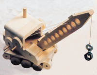
This crane is a great project that’s certain to provide lots of fun…not only for the child who plays with it…but for the woodworker who builds it, as well.
When completed, the cab will rotate a full 360-degrees -- the boom will raise and lower -- and the hook will go up and down. Added to these features is a simple “push/pull” locking mechanism on the boom and hook cranks. And although this may look like a complicated toy to build, it’s really quite easy.
I used clear pine stock, hardwood dowels and yellow woodworker’s glue for the basic construction. All the wheels were made with hole saws and arranged on the crane to give the illusion of being a tracked (bulldozer or tank-like) vehicle.
For the letter references in these instructions below refer to the related diagrams.
STEP 1:
Cut all the parts to size according to the list of materials — except for the cab sides (F), which will be cut out in Step 3, below. Use a 1-3/8-inch hole saw to cut out the large, 1-1/4-inch wheels (B); a 1-1/8-inch hole saw to cut out the smaller 1-inch wheels (C) plus an extra for the cab pivot pin lock (T); and a 1-5/8-inch hole saw to cut out the 1-1/2-inch crank wheels (P).
NOTE: If you can’t locate these exact size hole saws, you can use a larger diameter saw to cut them out, then mount them on your drill press and file or sand them down to the smaller sizes you need. The 7/8-inch diameter cab pivot pin lock (T) is made by sanding or filing-down an extra disc that’s been cut out with your 1-1/8-inch diameter hole saw.
STEP 2:
Make the chassis (A) by first laying out and drilling the 5/16-inch diameter axle holes. Then, use a bandsaw to cut the 30-degree bevels on the ends. Drill the 1-inch diameter by 1-inch deep hole for the cab pivot pin lock (T).
STEP 3:
Make the cab by first drawing all the contours and locating the holes for the cab sides (F) on a piece of 3/4-inch stock. Drill the 3/8-inch holes for the wheel axles (Q). Cut out the side design on the bandsaw or scroll saw. Resaw this piece on the bandsaw to get the two (approximate) 3/8-inch thick cab sides. Don’t drill the 1/4-inch diameter crank lock holes yet. We’ll do this later.
Next, drill the 3/8-inch diameter by 1/2-inch deep hole in the bottom of the cab floor (G) for the cab pivot pin (S). Screw two small screw-eyes into the cab rear panel (H). Glue the cab sides (F)., cab floor (G). and cab rear panel (H). together. When gluing the sides in place, temporarily slip (do not glue) one or two 3/8-inch dowels through the crank axle holes for alignment. Do not glue the roof on at this time.
STEP 4:
Make the cab roof (J) and counterweight (U) . Round the top and side edges of the roof on your belt or disc sander. Then, drill the 1/2-inch hole for the exhaust stack (V) . Glue the stack into position and install the 1/4-inch screw-eye. Set the roof aside.
Round the rear outside edges of the counterweight (U) and glue and clamp it to the cab assembly.
STEP 5:
Make the crank assemblies. Using a 3/8-inch diameter drill bit, enlarge the 1/4-inch diameter holes in the crank wheels (P) that were left by your hole saw’s pilot drill. Drill the offset 1/4-inch diameter holes in each crank wheel for the crank wheel handles. Slide each of these crank wheels onto the 3/8-inch diameter crank axles (but don’t glue them yet).
With a 1/4-inch drill bit mounted in a portable electric drill, insert the bit through the crank wheel handle hole you just drilled and use it as a guide to drill a series of four half-deep holes at approximate 90-degree intervals in the rotation of each crank handle. During assembly, be sure to put the cranks on the right side for right-handers…or the left side for left-handers.
Drill the 1/8-inch diameter string holes in the crank axles (Q) (see diagram). Sand the axles so they move freely where they pass through the cab mounting holes. Don’t sand the very ends of the axles where they go into the crank wheels. You’ll need a tight fit, here.
Assemble and mount the crank wheels (P) , crank handles (R) and crank axles (Q) with glue so each end of each axle is flush with the outer surface of a crank wheel. When assembled, there must be enough “play” to allow the assemblies to move side-to-side so the boom and hook positions can be locked and unlocked by engaging the protruding ends of the crank handles (R) in the holes you drilled in the cab side. Remember that the crank/axle with a single string hole goes in the top forward position on the cab.
IMPORTANT: When gluing crank handles (R) into crank wheels (P) , be sure the handles each protrude about 3/16-inch beyond the back side of their crank wheels. These protruding handle pins are engaged in the half-deep 1/4-inch holes you drilled in the cab side, acting as stops to hold the boom and hook in position during play.
STEP 6:
Make the cab pivot lock assembly by drilling a 3/8-inch diameter hole in the cab pivot pin lock (T), then gluing the cab pivot pin (S) into (T).
Now, drill a 7/16-inch hole in the center of platform (E). Once the pivot lock assembly above has dried, drop the pivot pin lock (T) with pin (S) attached and protruding through platform (E) into the 1-inch x 1-inch hole you drilled in the chassis (A), in Step 2.
Spread glue on the chassis (A)…(being careful not to get any glue near the center pivot pin area)…and glue the platform (E) to the chassis (A).
STEP 7:
Make the crane boom (K) by first drilling the holes according to the drawing. There are nine 3/4-inch “lightening” holes, a 7/16-inch hole at the base for the anchor pin (N) and two 1/8-inch cable run holes. Drill the 1/8-inch holes in the hook cable guides (M). Cut out the boom using the bandsaw or scroll saw and sand smooth. Glue the hook cable guides (M) into place and set aside to dry.
Drill the 3/8-inch boom mounting holes in the boom supports (L). Line up these holes with the ones in the cab sides (M) using the crane anchor pin (N) and glue the supports into place. Keep the glue away from the holes, because once the supports have had a chance to set up, you’ll have to remove the anchor pin to slip the boom into position between these two supports.
Now, mount the boom into the cab assembly by gluing the crane anchor pin (N) into place.
NOTE: Be careful not to get any glue in the center area of the anchor pin where the boom pivots on it.
Sand the axles (D) where they pass through the chassis (A) and then glue the wheels (B & C) into place.
STEP 8:
Stringing the boom. Begin by cutting a 30-inch length of twisted nylon cord and tying a knot in one end. Singe the end of the cord with the knot using a match or a lighter to prevent the knot from loosening. String the boom cable line through one of the holes in the bottom/rear crank axle. Pass this through one of the screw-eyes in the cab rear, then through the 1/8-inch hole that runs side-to-side near the tip of the boom. Now, bring this same cord back down through the other screw eye in the cab back…then into the other hole in the bottom/rear crank axle.
When the boom is in its horizontal-most position, pinch the line up against the crank axle hole. Now, raise the boom to a full vertical position and tie a knot where you’re pinching it. The line should be taut when the boom is dropped back to the horizontal position. Adjust the knot if the line’s too loose. Raise the boom, pull out the line and singe this end of your knot . . . just as you did the other.
STEP 9:
Stringing the hook assembly. Start by pinching one end of the small S-Hook around two 1/2-inch washers. Set this aside. Cut a 36-inch length of cord, tie a knot in one end and singe it as you did the other. Pass the line through the hole in the top/forward crank axle, then through the screw-eye in the roof (remember…the roof is still loose at this point).
Now, pass the line through the two cable guides (M) on the top surface of the boom and down through the 1/8-inch hole that runs top-to-bottom through the very tip of the boom. Tie this end of the line to the S-Hook. Hold the roof in place while you raise and lower the hook using the crank. If everything works properly, glue the roof in place.
Enjoy!